Description
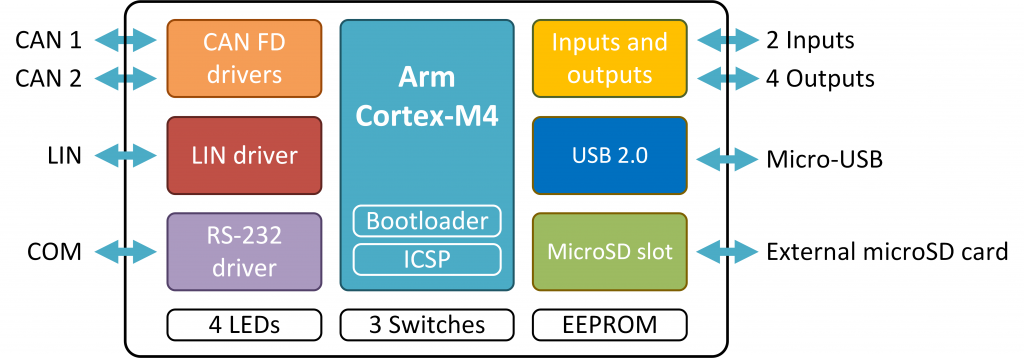
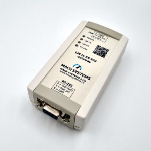
The CAN-FD LIN Gateway is a freely programmable converter/interface/data-logger that features two CAN(/FD) channels, a LIN channel, and a RS-232 port. The converter also offers a USB port, a microSD card slot and multiple digital/analogue inputs and outputs, and its firmware can be developed in C or C++. The device is suitable for a broad range of applications such as protocol conversion, network bridging, data logging, rest-bus simulation, and external peripheral control and monitoring.
CAN FD LIN Gateway User Manual
Features
- Two CAN-HS channels with CAN FD support
- LIN channel
- RS-232 port
- MicroSD card slot
- 4 digital outputs
- 2 analogue/digital inputs
- 4 status LEDs
- 32-bit Arm Cortex-M4 MCU
- Freely programmable in C/C++ language
- Free-of-charge IDE and C/C++ compiler
- Programming examples available
- Firmware upload over USB, CAN, RS-232 or ICSP
- On-board 16 Kbit EEPROM
- Externally or USB-powered
- Table-top use or DIN-rail mount
Firmware can be developed in C/C++ and can be transferred into the device over USB, CAN, RS-232, or a standard ICSP SWD interface, which also offers code debugging. The device is based on a STM32G4 Arm Cortex-M4 MCU and comes with a free-of-charge IDE, GNU C/C++ compiler, and programming examples.
The on-board EEPROM memory can store user’s application parameters, and the microSD card slot enables the user to load or save large data sets for simulations and data-logging purposes.
The four digital outputs (PWM capable) and the two analogue/digital inputs allow for both input and output triggering. The inputs can read 0-5 V analogue signals, and the outputs offer various output stages (push-pull, HSD, LSD) with currents up to 1.5 A enabling to easily control relays, valves, and other peripherals.
Use Cases
- CAN FD to CAN bridge
- LIN to CAN/CAN FD gateway
- CAN/LIN bus to RS-232
- Data logging
- Communication simulation
- ECU emulation
- Remote monitoring of inputs
- Remote control of outputs
Technical Specification
| Communication and Peripherals | ||
| Channels | 2 CAN-HS (ISO 11898-2) with CAN FD support (ISO 11898-1:2015; CAN 2.0A/B, ISO CAN FD) 1 LIN bus (supports both master and slave; ISO 17987; LIN 2.2a) 1 RS-232 1 Virtual COM port (USB 2.0 CDC) |
|
| Inputs | 2 Analogue/digital inputs (0-5 V) | |
| Outputs | 4 Digital outputs (PWM capable) DO1: HSD (5 V, max. 0.5 A) DO2, DO3: push-pull (5 V, max. 0.5 A) DO4: LSD (max. 40 V, 1.5 A) |
|
| Programming | Free-of-charge IDE and GNU C/C++ compiler (STM32CubeIDE) Programming examples available |
|
| Firmware update | over USB, CAN, RS-232, or ICSP (ST-LINK) | |
| Debugging | ST-LINK SWD (a programming header needed) | |
| Non-volatile memory | Internal 16 Kbit EEPROM External microSD card slot (a card is not part of delivery) |
|
| LEDs | 3 Dual-color LED 1 Power LED |
|
| Electrical | ||
| Power | External 7 – 30 V DC with polarity protection over DSUB connector USB-powered over Micro-USB (not for LIN bus) |
|
| Consumption | 100 mA @ 12 V (approx. 1 W) Note: When no digital output (DO1-DO4) is being driven. |
|
| MCU | STM32G483 (Arm® 32-bit Cortex®-M4) with DSP and FPU; 170 MHz, 512 KB Flash, 128 KB SRAM |
|
| Transceivers | CAN-FD: MCP2562FD LIN: MCP2003B |
|
| Mechanical | ||
| Connectors | 1 D-SUB9M 1 D-SUB9F 1 MicroSD slot 1 Micro-USB |
|
| Buttons and switches | 2 DIP switches 1 Tactile switch |
|
| Dimensions (L x W x H) | 108 x 54 x 30 mm | |
| Weight | 85 g | |
| Operating temperature | -20 to 70 °C | |
| Protection | IP20 | |
| Placement | Table (adhesive pads included) DIN-rail mount (clip sold separately) |
|
SDK and libraries
STM32CubeIDE project with examples of all device’s peripherals is available on our GitHub account.
Connector pinout
| CN1 | CN2 | |||
|---|---|---|---|---|
| Pin | Name | Note | Name | Note |
| 1 | DO1 | 5 V HSD | DO3 | 5 V push-pull |
| 2 | CAN1_L | CAN2_L | ||
| 3 | GND | GND | ||
| 4 | LIN1 | RS-232 RxD | In | |
| 5 | GND | GND | ||
| 6 | AI1 / DI1 | 0 – 5 V | DO4 | LSD |
| 7 | CAN1_H | CAN2_H | ||
| 8 | DO2 | 5 V push-pull | RS-232 TxD | Out |
| 9 | Vin / Vbat | AI2 / DI2 | 0 – 5 V | |


