Description
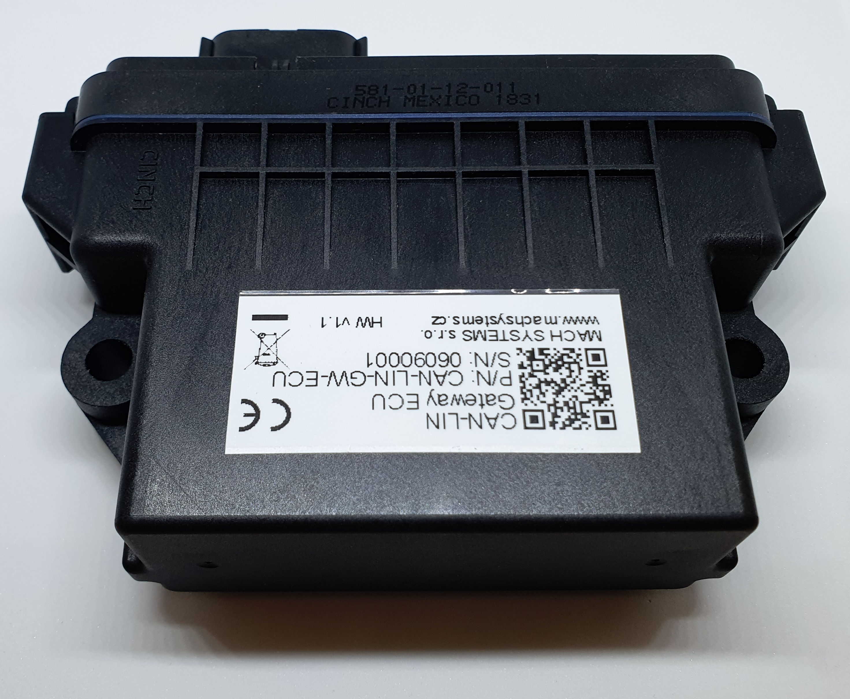
The CAN-LIN Gateway ECU is an electronic control unit that features up to two CAN/CAN FD channels, a LIN channel, and several multi-purpose digital/analogue inputs and outputs.
The control unit is fully configurable by the user and can be used as a stand-alone data converter between a CAN/CAN FD network and a LIN bus, or as a remote I/O module to interface sensors and actuators to CAN and LIN systems. The control unit supports both SAE J1939 and raw CAN protocols, and is suitable for stationary and mobile applications in harsh automotive and industrial environments.
CAN LIN Gateway ECU Data Sheet
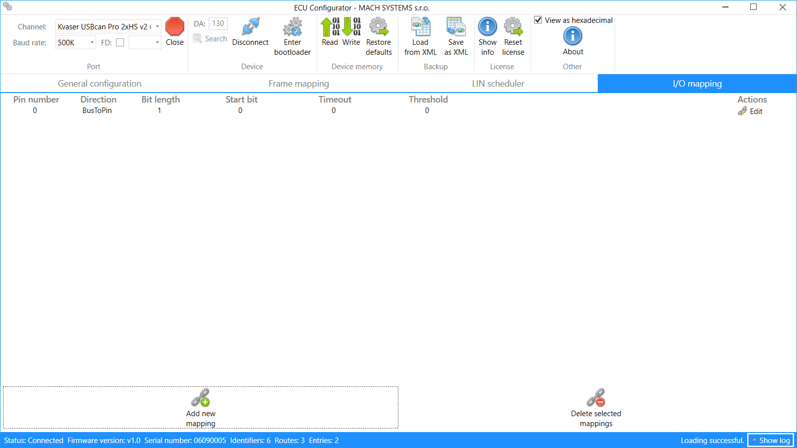
An essential product to be purchased along: ECU Configurator – a PC application for configuring the ECU over CAN bus.
Features
- Data conversion between CAN, CAN FD and LIN buses
- One CAN channel
- One CAN FD channel (optional)
- One LIN channel
- SAE J1939 support
- Configurable frame and data routing between channels
- Up to seven multi-purpose inputs and outputs with current measurement
- Configurable I/O mapping onto CAN or LIN frame data
- PC tool for easy configuration
- Waterproof automotive-grade ECU
- Suitable for 12 V and 24 V systems
- ECE-R10 (E1) approval (planned for 2021/Q4)
- Customisation on request
Usage Examples
-
- CAN – LIN bridge
- CAN – CAN FD gateway
- Remote I/O ECU
- Universal SAE J1939 ECU
The ECU Configurator PC application allows to easily configure the ECU over CAN bus. The user can set ECU’s mode, communication channel’s parameters, inter-channel frame conversion (frame mappings), and I/O mappings. The configuration is stored in the device’s non-volatile memory. The ECU Configurator can be purchased with or without a Kvaser CAN-USB interface.
The CAN-LIN Gateway is available in several variants that offer combinations of single-CAN / dual-CAN (CAN FD supported), with/without CAN termination, and automatic wake-up and sleep based on CAN bus activity / control over the ignition switch (KL15) input signal.
Technical Specification
| Communication Channels | |
| CAN | CAN 2.0B (baud rates: 125 / 250 / 500 / 1000 KBaud) Wake-up capable Bus termination: optional (see Ordering Information) |
| LIN | LIN v2.2a (baud rates: 9600 / 10417 / 19200 Baud), supports both Master and Slave, and Classic/Enhanced checksums; User-configurable LIN Master’s scheduler |
| CAN FD | ISO CAN FD (baud rate up to 8 MBaud): optional
Bus termination: optional see Ordering Information |
| CAN bus protocols | SAE J1939, Raw CAN |
| Inputs and Outputs | |||
| Number of Channels | 4 – 7 (see Ordering Information) | ||
| Channel Mode | Configurable: Analogue/digital input, HSD output | ||
| Analogue Inputs | 0 – 30 V, 12-bit ADC, sample rate 10 ms | ||
| Digital Inputs | Configurable voltage threshold | ||
| Digital Outputs | HSD with short-circuit protection and current measurement; PWM capable; Max. current 1.5 A per channel (2 A in total for IO1-4 and IO5-IO7) |
||
| Mapping | Inputs and outputs can be mapped onto LIN and CAN frame data bytes | ||
| Electrical and Mechanical | |||
| Input Voltage | 7 – 30 V DC | ||
| Power Consumption | Operation: 0.04 A @ 12 V (+20 °C)
Sleep: 40 µA @ 12 V (+20 °C) |
||
| Power Management | Options (see Ordering Information):
· Automatic wake-up and sleep based on CAN bus activity · KL15 (Ignition key switch) signal |
||
| MCU | 16-bit Automotive DSP | ||
| Firmware | Firmware update over CAN bus | ||
| Connector | 12-pin Molex MX150 Mating connector: Molex 33472-1201 (p/n: GW-ECU-CONNECTOR-12p) |
||
| Dimensions (L x W x H) | 130 x 75 x 43 mm (5.12” x 2.95” x 1.69” in) |
||
| Weight | 175 g (0.386 lb) | ||
| Operating Temperature | -40 to 85 °C (-40 to 185 °F) | ||
| Ingress Protection | IP67 |
| Certifications and Tests | |
| Road Vehicles | ECE-R10 (E1) approval (planned for 2021/Q4) |
| Transient Pulses | ISO 7637-2 |
| EMC | CISPR 25 |
| ESD | EN 61000-4-2 |
| Vibrations | EN 60068-2-27 EN 60068-2-64 |
| User Configuration | |
| ECU Modes | · Gateway: Configurable bi-directional frame mapping between CAN and LIN channels, digital and analogue inputs and outputs mappable onto CAN or LIN data frames.
· SAE J1939: ECU’s inputs and outputs are available over PGNs. Dynamic addressing and DM1 supported. |
| Communication Channel’s Parameters | CAN and CAN FD: Baud rate, sample point
LIN: Baud rate, Checksum type, Master/Slave, scheduling table for LIN Master |
| Configuration | User’s configuration is stored in the ECU’s non-volatile memory. |
| PC Application | ECU Configurator is a Windows application that allows to easily configure the ECU over CAN bus. |
Ordering Information
ECU
| Product Number | CAN Channels | LIN Channel | I/O | Wake-up | Pinout Type | |||
| CAN1 (CAN 2.0B) |
CAN2 (ISO CAN FD) |
On-board Termination | CAN1 | KL15 | ||||
| CAN-LIN-GW-ECU | • | • | 7 | • | A | |||
| CAN-LIN-GW-ECU-KL15 | • | • | 6 | • | A | |||
| CAN-LIN-GW-ECU-term | • | • | • | 7 | • | A | ||
| CAN-LIN-GW-ECU-term-KL15 | • | • | • | 6 | • | A | ||
| CAN-LIN-GW-ECU-CANFD | • | • | • | 5 | • | B | ||
| CAN-LIN-GW-ECU-CANFD-KL15 | • | • | • | 4 | • | B | ||
| CAN-LIN-GW-ECU-CANFD-term | • | • | • | • | 5 | • | B | |
| CAN-LIN-GW-ECU-CANFD-term-KL15 | • | • | • | • | 4 | • | B | |
Accessories
| Product Number | Description |
| GW-ECU-CONFIG-TOOL | PC configuration tool (without a Kvaser interface) |
| GW-ECU-CONFIG-TOOL-KVASER-IF | PC configuration tool including a CAN-USB Kvaser Leaf v3 interface |
| GW-ECU-CONNECTOR-12p | Mating connector including 12 female terminals
(Molex 1 pc 33472-1201 and 12 pcs 33012-2002) |
| GW-ECU-HARNESS-12p-1m | Cable harness with 12-pin connector for development and prototyping; length 1 m |


